
 |
| LM Descent |
DOI (Descent Orbit Insertion)
The DOI, which is a short retrograde maneuver of approximately 75 fps (delta V), is performed with the LM descent engine and is made at a position in the orbit 1800 from Powered Descent Initiation (PDI) point, which is the second descent maneuver.
| Typical ascent Hohmann transfer orbit, yellow labelled 2, from a low orbit, green (1) to a higher orbit, red (3). |
The purpose of the DOI is to reduce efficiently (with Hohmann-type transfer) the orbit altitude from approximately 60 nautical miles to 50 000 feet in preparation for PDI. Performance of continuous powered descent from altitudes much greater than 50 000 feet is inefficient, and a PDI at lower than 50 000 feet would be a safety hazard.
PDI (Powered Descent Initiation)
The whole LM powered-descent takes about 12 minutes and the main engine runs all the time.
 |
| LM powered descent in detail (about 12 minutes) |
The LM powered-descent trajectory design was established as a three-phase maneuver (following figure) to satisfy the operational requirements imposed on such a maneuver. PDI was also the zero time for all the following computer events (TFI Time From Ignition).
 |
| Powered Descent Phases |
1) Braking Phase (Ignition to high gate)
The first operational phase, called the braking phase, is designed primarily for efficient propellant usage while the orbit velocity is being reduced and the LM is guided to high-gate conditions for initiation of the next phase.
2) Approach Phase (High gate to low gate)
The second operational phase was called the approach phase. The term "high gate" is derived from aircraft-pilot terminology and refers to beginning the approach to an airport. The approach phase is designed for pilot visual (out of the window) monitoring of the approach to the lunar surface.
3) Landing Phase (Low gate to touch down)
The final operational phase or landing phase, which begins at low-gate conditions (again from aircraft-pilot terminology), is designed to provide continued visual assessment of the landing site and to allow pilot takeover from automatic control for the final touchdown on the lunar surface.
Mission-Planning Flexibility and Future Recommendations /6/
Many problems were encountered because original system designs were molded too closely to a nominal trajectory. Therefore, it is imperative that the mission planners define a flight regime for the system designers, as opposed to only a reference or nominal pirofile. Just as the system designers should not be arbitrarily conservative in defining performance, neither should the mission planners do so in defining the flight regime. This would place unnecessary requirements on system designs and result in either degrading the performance where it is really needed or increasing the development and test costs, or both. The mission planners must define the flight regime which optimizes the balance between mission objectives (including crew safety) and system capabilities. This reginie will change when either objectives or capabilities change. Thus, the mission planners’ design must maintain the capability or flexibility to accommodate reasonable changes in both. This capability must exist not only during system development but also after the systems become operational.
 |
| Apollo mission planning |
For example, in the initial development of the guidance-computer software, the descent targets were allocated to fixed (hardwired) memory. Erasable memory was quite limited and reserved primarily for system performance coefficients that might change because of final test results reported after computer rope manufacture.
 |
| Apollo AGC 1024-bit erasable core memory module (front and back). |
Posisition of the landing site was the only descent-trajectory-dependent parameter in eraseble load. This completely destroyed the mission planners’ capability for operational fexibility after manufacture of computer ropes (which can occur several months before launch).
 |
| AGC rope memory (read-only type) was slow to make |
After it was pointed out several times that system capabilities as well as mission objectives would be, enhanced by targeting changes based on latest system test results, the targets were placed in erasable memory. Without this capability, the efficiency and adequacy of mission planning would have been severely hampered.
 |
| During the landing phase the pitch angle was moderate to allow better view to the landing point. |
One recommendation for changing the design concept for future landing programs (beyond Apollo) is offered. The navigation concept based on surface tracking along the approach can severely limit the flexibility of landing-site selection. This concept demands the generation of considerable data from previous missions or programs and can be the constraining factor in deleting some scientifically desirable sites. A navigation technique based on direct ranging to the landing site during approach provides greater flexibility for site selection.
 |
| Direct ranging using LR (Landing Radar) and LPD (Landing Point Designator) |
As a result of the Apollo 11 postflight analysis, only two minor changes were incorporated in descent planning for the Apollo 12 flight. The first change was the provision for a navigation update of the landing site early in the braking phase to enhance the pinpoint landing capability. The second change was a slight modification to the descent targeting to enhance the landing-site redesignation and manual translation capability in the approach and landing phases.
 |
| LPD (Landing Point Designator) on the left LM double window (Commander's window). |
The Apollo 12 lunar module descent and ascent data also correlated well with premission planning. During lun'ar module descent, the landing-site navigation update and redesignation capabilities were used, along with manual maneuvering, to achieve the first pinpoint lunar landing. The landing, within 600 feet of the Surveyor III spacecraft, has provided confidence for premission planning of future manned lunar-exploration missions.
 |
| LPD on the LM commander's double window (you need to have your eye on an exact spot to just see a single image and there you can see the right angle over the terget point). |
From the Apollo experience, it has been shown that many mission-planning prob lems were encountered as a result of changing system capabilities and constraints. These problems were solved in the Apollo Program and can be avoided in future programs by
 |
| LPD Marking Details |
(1) proper understading by the mission planners and the system designers of all objectives and requirements;
(2) proper definition and modeling of system performances;
(3) awareness and understanding of system interfaces;
(4) definition of a design flight regime, not just a nominal trajectory;
(5) maintenance of a capability for mission-planning flexibility; and
(6) avoidance of false conservatism in defining system performances and flight regimes.
Only one recommendation for changing the design concept for future lunar-landing programs (beyond Apollo) is offered. It is recommended that a navigation technque based on direct ranging to the landing site be investigated to replace surface tracking along the approach. This would provide greater flexibility for site selection in areas of rough-approach terrain.
TABLE 1. - APOLLO 11 PREMISSION POWERED-DESCENT NOMINAL EVENTS
| Event | TFI, nim:s | Inertial velocity, fps | Altitude, ft | deltaV, fps |
| RCS Ullage | -0:07 | |||
| Powered descent initiation | 00:00 | 5560 | 48 814 | 0 |
| Throttle to maximum thrust | 00:26 | 5529 | 48 725 | 31 |
| Rotate to windows-up position | 02:56 | 4000 | 44 934 | 1572 |
| LR altitude update | 04:18 | 3065 | 39 201 | 2536 |
| Throttle recovery | 06:24 | 1456 | 24 639 | 4239 |
| LR velocity update | 06:42 | 1315 | 22 644 | 4399 |
| High gate | 08:26 | 506 | 7 515 | 5375 |
| Low gate | 10:06 | LSV 68 | 512 | 6176 |
| Touchdown (probe contact) | 11:54 | LSV 0 | 12 | 6775 |
TFI - Time From Ignition (PDI)
LSV - Lunar Surface Velocities, horizontal velocity relative to the lunar surface.
 |
| Charles Stark Draper with Wernher von Braun |
Don Eyles /8/: "The job of designing the guidance system for Apollo spacecraft had fallen to the MIT Instrumentation Laboratory in Cambridge, Massachusetts. Under the leadership of its founder "Doc" Charles Stark Draper, the Lab had since 1939 played the preeminent role in perfecting inertial guidance systems. Our contract to design and program the Apollo Primary Guidance and Navigation System (PGNS, pronounced "pings") was the first Apollo contract signed. Doc had volunteered to fly the mission himself. It was LUMINARY revision 99 that flew the Apollo 11 mission in July, 1969. Revision 116 flew Apollo 12 in December, and so on." [Don Eyles was one MIT programmer of the LM descent phase software.]
 |
| Descent Phases |
 |
| LM Three-Phased Powered Descent |
BRAKING PHASE
The intended landing area, designated Apollo site 2, in the Sea of Tranquility is centered at latitude 0.60 N and longitude 23.50 E. The major events occurring during the braking phase are tabulated in table I and shown in the previous figure.
The braking phase is initiated at a preselected range approximately 260 nautical miles from the landing site near the perilune of the descent transfer orbit at an altitude of approximately 50 000 feet. This point is the Powered Descent Initiation point (PDI) and also the zero time for the following descent events. The DPS (Descent Propulsion System) ignition starts the timers to measure events at some Time From Ignition (TFI). The whole descent to the moon is done in about 12 minutes TFI.
The PDI ignition is preceded by a 7. 5-second RCS (Reaction Control System) ullage burn to settle the DPS propellants. The DPS (main descent engine made by TRW) is ignited at trim (10 percent) throttle. This throttle setting is held for 26 seconds to allow the DPS engine gimbal to be alined (or trimmed) through the spacecraft center of gravity before throttling up to the maximum or fixed throttle position.
The braking phase is designed for efficient reduction of orbit velocity (approximately 5560 fps) and, therefore, uses maximum thrust for most of the phase (from 0:26 to 6:24 TFI). However, the DPS is throttled during the final 2 minutes of this phase for guidance control of dispersions in thrust and trajectory.
 |
| LM Descent Engine Duty Cycle (about 1000 s with a small calibration run at installation time) |
The DPS is throttleable only between 10 and 60 percent; therefore, during FTP (Full Throttle Position) operation, the guidance is targeted such that the commanded quadratic acceleration, and consequently the command thrust, is a decreasing function.
Only when the command decreases to 57 percent, a 3-percent low bias, the DPS is throttled as commanded. Above that the DPS is commanded to full thrust.
 |
| Various LM attitudes during descent |
The thrust axis must point so that the deceleration is as planned. The Apollo 11 crew rotated around the thrust axis in a windows-down attitude for visual ground tracking. Rotation to a more normal attitude is performed at an altitude of approximately 45 000 feet, so that the LR (Landing Radar) can acquire the lunar surface to update the guidance computer estimates of altitude and velocity. Altitude updating is expected to begin at an altitude of approximately 39 000 feet; velocity updating is expected to begin at approximately 22 000 feet (see table 1).
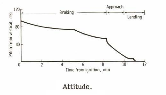 |
| Apollo 11 LM attitude (pitch) angles during powered descent |
HIGH GATE (8:26)
The braking phase is terminated when the guidance-calculated TGO to achieve targets is reduced to 60 seconds (to avoid the division by zero at TGO 0 sec). Termination occurs at an altitude of approximately 7000 feet, a range of approximately 4.5 nautical miles from the landing site, and a time from ignition (TFI) of 8 minutes 26 seconds. The guidance computer automatically switches programs and targets from P63 to P64 to begin the approach phase, as explained in the previous section. (More detailed description of programs is later in this text.)
 |
| Approach / visibility and landing phase |
APPROACH (OR VISIBILITY) PHASE
The approach phase (se the previous figure) provides visual monitoring of the approach to the lunar surface. That is, the guidance (P64) is targeted to provide spacecraft attitudes and flight time adequate to permit crew visibility of the landing area through the forward windows throughout the approach phase. At high gate, in addition to the guidance-program switch, the LR antenna is changed from position 1 to position 2 for operation near the lunar surface. The trajectory-approach angle (glide angle) is shown to be approximately 16° relative to the surface. This angle allows the crew visual line of sight to the landing area to be above the sun angle (10.9° nominal to 13.6° maximum) even in dispersed situations.
 |
| Visibility angles: for Apollo 11 LM Sun elevation (SEA) was 10.9 degrees and view elevation (VEA) 16 degrees. |
Since Apollo 11 LM pitch was 45 to 0 degrees during the approach phase, and since VEA was 16 degrees, the down look angle to the landing point was 16-39 degrees.
The angle above the sun line is desirable because surface features tend to be washed out when looking along or below the sun line. During the approach phase, the altitude decreases from 7000 to 500 feet, the range decreases from approximately 4.5 nautical miles to 2000 feet, and the time of flight is approximately 1 minute 40 seconds. Although no guidance changes or other transients are made, operationally, the approach phase is considered to be terminated at an altitude of 500 feet (low gate), at which point the landing phase begins.
LANDING PHASE
The landing phase is designed to provide continued visual assessment of the landing site and to provide compatibility for pilot takeover from the automatic control. No change occurs in guidance law or targets at this point (low gate) because the approach-phase targets have been selected to satisfy the additional constraints. The approach- and landing-phase targets (P64) yield conditions for initiating the automatic vertical descent from an altitude of approximately 150 feet at a 3-fps altitude rate. These conditions, along with the selected acceleration and jerk targets, yield trajectory conditions of 60 fps of forward velocity, 16 fps of vertical descent rate, and an attitude of approximately 16° from the vertical at a 500-foot altitude.
 |
| Apollo 11 LM landing phase angles and LPD view. |
These conditions were considered satisfactory by the crew for takeover of manual control. Should the crew continue on automatic guidance, at a TGO of 10 seconds, P65 (the velocity-nulling guidance) is automatically called to maintain the velocities for vertical descent to the lunar surface. Probes that extend 5.6 feet below the LM landing pads, upon making surface contact, activate a light which signals the crew to shut down the DPS manually, whether automatic or manual guidance is being used.
 |
| Nominal commander's view during the landing phatse |
POWERED DESCENT GUIDANCE THEORY
The basic LM descent guidance logic is defined by an acceleration command which is a quadratic function of time and is, therefore, termed quadratic guidance.
 |
| LM Quadratic Guidance |
The current LM position vector R and velocity vector V are determined from the navigation routine. The desired (or target) position vector RD', velocity vector VD', acceleration vector AD', and down-range component of jerk jDZ are obtained from the stored memory. (Jerk is the time derivative of acceleration.) The down-range (horizontal) components of these state vectors (current and desired) are used in the jerk equation to determine the time to go (TGO); that is, the time to go from the current to the desired conditions.
 |
| Position vector R and velocity vector V. |
If the TGO, the current state vector, and the desired state vector are known, then the commanded acceleration vector AC is determined from the quadratic guidance law. Note that the acceleration-command equation yields infinite commands when the TGO reaches zero. For this reason, the targeting is biased such that the desired conditions are achieved prior to the TGO reaching zero. By using spacecraft mass M, calculating the vector difference between the commanded acceleration and the acceleration of lunar gravity G, and applying Newton's law, a commanded thrust vector TC can be found. The magnitude of TC is used to provide automatic throttling of the DPS. When the throttle commands exceed the throttle region of the DPS (10 to 60 percent of design thrust), maximum thrust (FTP) is applied. The vector direction is used by the DAP (Digital Auto Pilot) to orient the DPS thrust by either trim gimbal attitude commands or RCS (Reaction Control System) commands to reorient the entire spacecraft
 |
| During LM descent engine thrust, gimbal angles (pitch and roll) and RCS jets (4 glusters of 4 jets, timed bursts) were controlled. |
These Quadratic Guidance Equations were precisely developed for LM lunar descents. They were approximated by terms up to 4th order in the position, and 2nd in the acceleration. Thanks to a Newton-Rhapson iteration technique, the Time-to-Go (TGO) and an acceleration command can be obtained.
During the powered descent, the guidance computer provides several sequential programs (P63 to P67) for guidance and control operations. The first program is P63, entitled "Braking Phase Guidance".
 |
| Don Eyles with Charles Draper |
Don Eyles /8/: "On July 20, 1969 the area on the second floor of 75 Cambridge Parkway where we monitored missions was crowded despite efforts to keep it clear for those of us who were most involved in this phase of the mission. We listned to a squawk box in a nondescript classroom, while a quarter of a million miles away a manned spacecraft emerged from behind the moon and approached its orbital low-point (perilune) of about 50,000 feet above the cratered surface, where the lunar landing burn would begin.
DSKY was used to enter commands to the LM computer (AGC)
The crew keyed in Verb 37 to select P63, the phase that controlled the preparations for the Powered Descent Initiation (PDI) and stayed in control until the burn achieved its firdt set of targets. The computer processed an algorithm to compute the exact time for ignition and the attitude the LM should be in at that time. Next the spacecraft maneuvered to that orientation. At the time of ignition the engine bell would be pointed almost dead ahead, directly opposing the spacecraft's orbital velocity.
 |
| LR Landing Radar antenna was located under the descent stage |
Now the computer issued code 500. It thought the landing radar antenna was in the wrong position. The crew saw that the relevant switches were alread in the right positions, but they cycled them anyway and the warning cleared. This had no connection with the events that would follow, but it nourished out suspicion of "discretes", those signals that told to the computer some fact like the position of a switch or an antenna - but sometimes lied.
Control passed to "BURNBABY" - the master ignition routine that we wrote after LM-1 to save memory by exploiting the similarities among the powered flight phases in the period leading up to ignition. Verb 06 Noun 62 appeared on the DSKY. The middle register contained a time in minutes and seconds that began to count down toward light-up (the descent ignition moment was the 0:00 time of the LM descent events that followed it [all times were measured TFI, Time From Ignition]). At 35 seconds the display went blank, and at 30 reappeared. This was a signal that Average-G had started. At seven and half seconds (before TFI), the ullage burn began. At five seconds (before TFI), the display flashed to request a "go" from the crew. Buzz ALdrin, the LM pilot, standing on the right side of the cockpit, had the main responsibility for working the DSKY. Now he just pushed PROCEED button on DSKY.
 |
| Apollo 11 crew: Commander Neil Armstrong, CM Pilot Mike Collins and LM Pilot Buzz Aldrin |
At Mission Elapsed Time (MET) 102:33:05 self-igniting propellants came together in the descent engine and it lit up at 10% throttle. Armstrong did not even feel the centle push - less than 1/25 G. The display changed to Noun 63 and the three display registers now showed a total velocity of 5559.7 ft/sec, an altitude-rate of -2.2 ft/sec, and an altitude of 49971 feet. The gimbals that pivoted the descent engine moved to align the thrust vector with the spacecraft's center of mass. Then, 26 seconds into the burn, the software throttled-up the DPS (Descent Propulsion System) or TRW descent engine to its maximum thrust of 9870 pounds (43,900 Newtons), 94 % of the engine's official rating of 10500 pounds, and at the same time enabled the descent guidance.
P63 was called the braking phase because its only purpose was to shed horizontal velocity. It would end (or throttle down) in about eight minutes when the spacecraft reached target conditions known as "high gate" at about 7400 feet altitude."
PROGRAMS
P63 - BRAKING PHASE GUIDANCE
Program 63 contains an ignition algorithm and the basic guidance logic. The ignition logic, which determines the time for the crew to ignite the DPS for PDI, is based on a stored, preselected surface range to the landing site. After descent-engine ignition, the basic guidance logic is used to steer the LM to the desired conditions for the beginning of the approach phase. As stated previously, the targets are selected with a bias such that the desired conditions are achieved prior to the TGO reaching zero. When the TGO reaches a preselected value, the guidance program switches automatically from P63 to P64, which is entitled "Approach Phase Guidance".
Braking Phase Program (P63) With AGS Preparation for Orbit Insertion (410+00000) /8/
Purpose of Braking Phase Program (P63) is to calculate required time of DPS ignition.
This procedure controls PGNCS during countdown, ignition, and thrusting of powered landing maneuver, to obtain desired aim conditions for braking phase. Successful accomplishment of braking phase aim conditions (high gate) is indicated to crew by automatic selection of Approach Phase Program (P64). P63 must be selected at least 20 minutes before nominal TIG for powered landing.
This procedure prepares AGS to steer LM by changing DPS thrust vector from retrograde (PGNCS braking phase) to postgrade to achieve orbit insertion.
Landing Analog Display Routine (R10) is enabled near start of average g in P63 and is terminated when average g is terminated.
U-jets and V-jets may be disbled (V65E) or enabled (V75E). This capability is intended to be used during Docked DPS Thrust Program (P40) with AGS Followup only. However, this capability is available during P63.
Following DSKY display is available during powered landing, to support manual throttle operations. (Auto command is not available for dsplay on THRUST ind during manual throttle.)
V16 N92E (DSKY Command: "Verb 16 Noun 92 Enter")
 R1 Desired auto throttle XXXXX% (may be >100% of FTP thrust)
 R2 H Rate   XXXX.X fps
 R3 H    XXXXX fps
ENG THR CONT: THR CONT sw - MAN is permitted at any time during powered descent. However, (in P63, P64) whenever GUID CONT sw - PGNS and S/C:PGNS sw - AUTO, care should be exercised that manual command does not exceed LGC desired thrust more than briefly; otherwise, LGC may invert LM in attempting to achieve targeted trajectory.
P64 - APPROACH PHASE GUIDANCE
Program 64 contains the same basic guidance logic as P63, but a new set of targets is selected to provide traj ectory shaping throughout the approach and landing phases and to establish conditions for initiating an automatic vertical descent from a low altitude to landing. In addition, P64 provides window-pointing logic for the LPD (Landing Point Designator) operation. That is, the landing point will be maintained along the LPD grid on the commander's window. During this time, the crew can make manual inputs with the attitude hand controller to change incrementally (down range or cross range) the intended landing site and remain in auto-matic guidance. When the TGO reaches a preselected value (none zero), the guidance program switches automatically from P64 to P65, which is entitled "Velocity Nulling Guidance".
Approach Phase Program (P64) /8/
Purpose of Approach Phase Program (P64) is to control PGNCS during thrusting, from completion of high gate aim conditions until completion of low-gate aim conditions; to control LM thrust and attitude in manner to provide visibility of presently designated landing site; and to provide landing site redesignation capability. Successful accomplishmnet of low-gate aim conditions is indicated by automatic selection of Landing Phase (ROD) Program (P66).
If desired:
Key V16 N68E
 R1 Horizontal range (to landing site) XXXX.X nm
 R2 TG XXBXX min-sec
 R3 VI (Inertial Velocity) XXXX.X fps
Following DSKY display is available during powered landing, to support manual throttle operations. (Auto command is not available for display on THRUST ind during manual throttle.)
V16 N92E
 R1 Desired auto throttle XXXXX% (may be >100% of FTP thrust)
 R2 H Rate XXXX.X fps
 R3 H XXXXX feet
ENG THR CONT: THR CONT sw - MAN is permitted at any time during powered descent. However, (in P63, P64) whenever GUID CONT sw - PGNS and S/C:PGNS sw - AUTO, care should be exercised that manual command does not exceed LGC desired thrust more than briefly; otherwise, LGC may invert LM in attempting to achieve targeted trajectory.
P65 - VELOCITY NULLING GUIDANCE
Program 65, which nulls all components of velocity to preselected values; is used for an automatic vertical descent to the surface, if desired. No position control is used during this guidance mode. The sequencing for automatic guidance is illustrated in the next figure.
 |
| Targets for automatic guidance and P numbers. |
Program 66, entitled "Rate of Descent", and program 67, entitled "Manual Guidance", are optional modes which can be used at crew discretion (manually called up through the DSKY) at any time during the automatic guidance modes (P63, P64, or P65).
P66 - RATE OF DESCENT, SEMIMANUAL PILOTED MODE
During P66 operation, the crew control spacecraft attitude, and the computer commands the DPS throttle to maintain the desired altitude rate. This rate can be adjusted by manual inputs from the crew and is normally entered late in P64 operation (near low gate) prior to P65 switching for manual control of the final touchdown position.
 |
| LM Commander could change the landing point (and for example Neil Armstrong did that 1969) |
Landing Phase (ROD) Program (P66) /8/ page 4.10-88
 |
| ACA Attitude Control Assembly |
Purpose of Landing Phase (ROD) Program (P66) is to modify LM rate of descent in response to manual inputs, via DES RATE sw, to LGC, and to modify inertial attitude in response to manual inputs via ACA.
 |
| ROD (Rate of Descent) switch in LM panel 5. |
In absence of manual control inputs, constant rate os descent and inertial attitude are maintained. P66 updates LM state vector with acceleration and landing radar data but inhibits landing radar updates below approximately 50 feet.
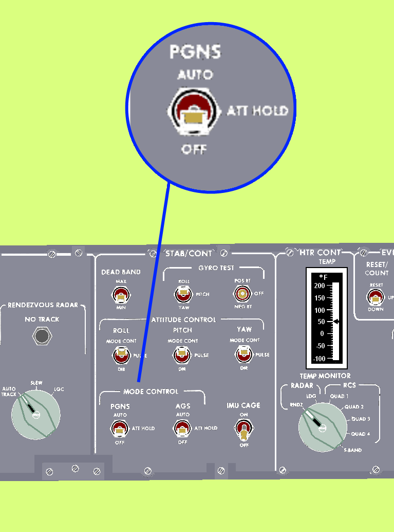 |
| S/G PGNS switch in panel 3 (AUTO, ATT HOLD and OFF) |
S/C:PGNS sw - AUTO causes LGC to null horizontal velocity by tilting thrust vector of vehicle up to 20 degrees.
With S/C:PGNS sw - ATT hold, the desired attitude to arrest the horizontal velocities is displayed on the FDAI attitude error needles (modulo 20 degrees).
If desired:
Key V06 N68E
 R1 Horizontal range (to landing site) XXXX.X nm
 R2 TG XXBXX min-sec
 R3 VI (Inertial Velocity) XXXX.X fps
Following DSKY display is available during powered landing, to support manual throttle operations. (Auto command is not available for display on THRUST ind during manual throttle.)
V16 N92E
 R1 Desired auto throttle XXXXX% (may be >100% of FTP thrust)
 R2 H Rate XXXX.X fps
 R3 H XXXXX feet
This allows backup ROD method, whereby LGC-calculated thrust required to achieve descent rate commanded by DES RT sw can be dispayed on DSKY for manual implementation (by either crewman) if required.
1. Observe PROG ind - P66
/P66 is automatically called during any phase of powered descent if S/C:PGNS sw - ATT HOLD and DES RATE sw - +1 FPS or -1 FPS, or from P64 when time TTF>TENDAPPR. Altitude rate at entry to P66 is maintained until modified by DES RATE sw inputs./
2. FL V06 N60
 R1 V (Forward) XXXX.X fps
 R2 H rate XXXX.X fps
 R3 H XXXXXX ft
 Poss PROG lt - on
 Key RSET
 Key V05 N09E (if feasible)
 01466 - <= TOOFEW engine throttle commands computed
  since last omitted throttle computation
 Key KEY REL
/TOOFEW is padloaded erasable quantity./
To perform manual altitude update of AEA:
Key DEDA C 223+XXXXXE (100ft)
/XXXXX must be nonzero. Address contents are reset to zero by AEA within 2 seconds, thus allowing later updates./
3. Monitor descent:
DES RATE sw - effect desired rate of descent
/DES RATE sw establishes rate of of descent in fixed increments; down (-) increases rate, up (+) decreases rate. Each actuation results in LGC change of 1 fps in rate of descent./
ACA - rotate to desired attitude and/or landing site
/Tilting descent engine thrust vector via ACA accelerates LM horizontally to rate that is maintained when thrust vector is returned to vertical./
WARNING
DES QTY warn lt will not be accompanied by MASTER ALARM; therefore, crewmen must monitor MPS: FUEL & OXID QUANTITY ind.
P67 - MANUAL GUIDANCE
Program 67 maintains navigation and display operations for complete manual control of the throttle and altitude. Normally, this mode is not used unless P66 is inoperative.
THE dV AND PROPELLANT REQUIREMENTS
The dV and propellant requirements are determined by the nominal trajectory design, contingency requirements, and dispersions. Consequently, these requirements have undergone continual change.
The required 6827-fps dV is established by the automatically guided nominal. In addition, 85 fps is added to assure 2 minutes of flying time in the landing phase, that is, below an altitude of 500 feet. The automatic guidance required only 104 seconds of flying time for the landing phase.
Also, a 60-fps dV is added for LPD operation in the approach phase to avoid large craters (1000 to 2000 feet in diameter) in the landing area. Contingency propellant allotments are provided for failure of a DPS redundant propellant flow valve and for bias on propellant low-level-light operation. The valve failure causes a shift in the propellant mixture ratio and a lower thrust by approximately 160 pounds, but otherwise, DPS operation was satisfactory.
The low-level light Signifies approaching propellant depletion; therefore, a bias is used to protect against dispersions in the indicator. If the low-level light should fail, the crew uses the propellant gage reading of 2 percent remaining as the abort decision indicator. The light sensor provides more accuracy and is therefore preferred over the gage reading.
The ground flight controllers call out time from low-level light "on" to inform the crew of impending propellant depletion for a land-or-abort decision point at least 20 seconds before depletion. This procedure allows the crew to start arresting the altitude rate with the DPS prior to an abort stage to prevent surface impact. The allowance for dispersions is determined from the Monte Carlo analysis mentioned previously. The margin is 301 pounds. This margin can be converted to an additional hover or translation time of 32 seconds.
REFERENCES
/1/ Apollo News Reference, 1968
/4/ MECHANICAL DESIGN OF THE LUNAR MODULE DESCENT ENGINE
Jack M. Cherne, Manager,
Engineering Design Department,
Power Systems Division, TRW Systems,
Redondo Beach, California, U.S.A.
/5/ APOLLO EXPERIENCE REPORT - DESCENT PROPULSION SYSTEM,
William R. Hammock, Jr.,
Eldon C. Currie, and
Arlie E. Fisher,
Manned Spacecraft Center, Houston, Texas 77058
/6/ APOLLO EXPERIENCE REPORT - MISSION PLANNING FOR LUNAR MODULE
DESCENT AND ASCENT, Floyd V. Bennett, Manned Spacecraft Center
/7/ LMA790-2 - Lunar Module Vehicle Familiarization Manual - Nov 1, 1969
/8/ Don Eyles - Tales from the Lunar Module Guidance Computer, 2004
/9/ YouTube videos:
"LM - Capcom" audio and
"LM - Flight Control" audio.
/10/ NASA TN D-8227 -
M. D. Holley, W. L. Swingle, S. L. Bachman,
C. J. LeBlanc, H. T. Howard, and H. M. Biggs -
APOLLO EXPERIENCE REPORT - GUIDANCE AND CONTROL SYSTEMS:
NAVIGATION, AND CONTROL SYSTEM DEVELOPMENT PRIMARY GUIDANCE, May 1976
/11/ NASA TN D-8086 -
D. Harold Shelton -
APOLLO EXPERIENCE REPORT - GUIDANCE AND CONTROL SYSTEMS -
LUNAR MODULE STABILIZATION AND CONTROL SYSTEM, November 1975
/12/ NASA TN D-7990 -
Kurten, P. M.:
Apollo Experience Report - Guidance and Control Systems:
Lunar Module Abort Guidance System., 1975.
/14/ NASA TN D-7289
Willium H. Peters, Kenneth J. Cox
APOLLO EXPERIENCE REPORT - GUIDANCE AND CONTROL SYSTEMS -
DIGITAL AUTOPILOT DESIGN DEVELOPMENT, June 1973
/15/ Wikipedia
/16/ Internet, Flicker
* * *


No comments:
Post a Comment