They are now using LEDs everywhere and LEDs will replace most fluorescent lights in the future. Let's have a look what they can do.
BTW: Regardless of LED color, Cree advises users not to look directly at any LED lamp.
Here are a couple of videos.
Some LED safty factors:
"All light sources have the potential to be harmful to both the skin and the eyes through UV, blue light (410-480 nm) and IR emission. Independent photobiological testing of Cree visible light LED lamps has confrmed that the only health risk of visible light LED lamps signifcant enough to warrant advisory is viewing blue light with the eyes. LED lamps that emit blue light may be called multiple names, such as Blue, Royal Blue or Dental Blue. In addition, many white LED lamps, including Cree’s, are based on blue LED die and contain signifcant blue light content. Therefore, Cree has tested its Royal Blue, Blue and White LED lamps for eye safety.
Cree’s testing to date indicates that Royal Blue and Blue (450-485 nm dominant wavelength) LED lamps pose a higher eye safety hazard than White LED lamps. Other colors of LED lamps, such as Green or Red, do not pose a defned eye safety risk. Regardless of LED color, Cree advises users not to look directly at any LED lamp."
"Dornier Do-X design work began in 1924 in Altenrhein, Switzerland and nearly a quarter million man-hours were expended over the next five years before full size wooden mockup of the aircraft was completed."
"A new feature was the division into three decks. The cockpit, the navigation and radio room and the machinery room were located on the upper deck, while the main deck with its luxurious furnishings provided seating for up to 66 passengers. The lower deck was used to store fuel and supplies. For the first time in the history of aviation, a one-to-one wooden mock-up of an aircraft was built. For the construction of the Do X, a special assembly hangar with a slipway had to be erected, the site selected being Altenrhein on the Swiss shore of Lake Constance."
After now using MNS (Master Navigator Software) for several years it is time to learn all those abbreviations used in the navigation terminology. Cross Track Error or XTE is the key word for the quality of guidance. If you can keep XTE at it's minimum it is proven that you made the shortest distance from point to point.
Picture: Cross Track Error (XTE)
Here is a typical MNS guidance screen.
Picture: MNS En Route Guidance Screen
XTE is shown on the right side blue window. At this moment we seem to be 898 meters left of the great circle between Nord and Npole (Nord and Npole are our waypoints) in this leg. When executing the route you should always keep XTE at it's minimum. The total leg distance is 920 km and it's true bearing is 0 degrees.
On the left side blue window you see several other parameters. Here they are explained:
WPT - Way point name
RTE - Route name
DST - Distance to way point or route end point
ETA - Estimated time of arrival to the way point or route end point
TTG - Time to go to the way point or route end point
An interesting video about A380 hi-lift devices. Notice that when using full flaps the small aileron becomes so inefficient that additional large span spoilers are needed. It is also interesting that the actual aileron is splitted to several parts and they seem to work sequentially: when one part is fully used the next part assists. The LAF (Load Alleviation Function) system must play a role here also.
Spoilers are sometimes called "lift dumpers". Spoilers that can be used asymmetrically are called spoilerons and are able to affect an aircraft's roll. For readers not familar with aircraft controls here is more basic information about it.
The flaps and slats are operated by long shafts and gear boxes from single motors located in the center of the fuselage as seen in the following picture. This is the noise heard in the videos.
SFCC stands for Slats & Flaps Control Computers.
Here is how the splitted aileron works and why it works as it does:
"The 380 has 3 ailerons per wing, an outer, mid, and inner, the inner aileron has an electrical back so the aircraft could be controlled even in the event of a total hydraulic failure.
For takeoff landing the ailerons deflect down a little, that is called the "Aileron Droop Function" (ADF), the objective of the ADF is to increase the high lift function performed by the slats and flaps. All the ailerons droop downwards (3 each side), when the flaps are extended. Ailerons and spoilers execute the roll function. Spoilers are needed at slow speed since ailerons only would be too unefficient for the roll function.
The ailerons also have another function called, "Load Alleviation Function" (LAF), the objective of the LAF is to reduce structure fatigue and static loads on the wing during manoeuvres and turbulence.Spoilers 6 to 8 and all the ailerons are involved in the LAF.
The LAF unloads the stresses on the wing by momentaraly deploying the flight spoilers and deflects ALL ailerons upward. The function is so fast that it is hardly noticable. I do not think that it makes the turbulance feel any worse though. The function seems to work very well.
These functions (apart from the electrical backup) are common on other Airbus types."
Some additional Airbus flight control documents (pdf format):
Since Bosch introduced CAN bus in 1980's it has been utilized in several other than car environments. Marine electronics uses it and call it NMEA 2000. Airplanes use it and they will call it ARINC 825. Since it is so famous here is a small and very informative tutorial to NMEA 2000 which uses CAN.
There is a nice new mobile PC computer (running Windows) from Panasonic that is rugged and that is more flexible for several applications than a laptop. Check the following videos.
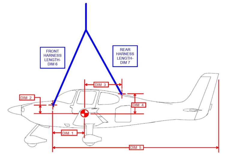
BRS parachutes have saved about 250 lives to this day. One parachute for a 500 kg airplane costs about 4.500 $. The following video tells how it works.
BRS Parachute System
Here is one story about how the parachute saved four lives.
Technical Details
The rocket launch tube and the handles
The canister assembly
The parachute is attached to the airframe at three hard points. The harness and the parachute is packed into the canister and the rocket is installed next to it. The rocket and the canister are usually somewhere inside the fuselage. Here are some pictures about the installation.
Different types of harness terminations
BRS-1050 Canister Installation in Apollo Delta Jet Trike
Here is some information about high G simulators from USA. The Blue Angels tested the ATFS-400 Phoenix and their test video tells most of it. At some points it is a bit choppy but otherwise it is the best next to the real F-18C fighter aircraft.
Blue Angels Visit NASTAR Center
The most difficult region for any centrifuge type high G simulator must be the region around zero G. When flying it is easy to produce zero G (see the picture below).
Flying zero G
With a centrifuge the region between +1 and -1 G is impossible. As soon as the centrifuge turns the gondola upside down there will be -1 G without any smooth transition from +1 G. The only way to produce zero G for small time periods is to have such a gondola that can be dropped to a free fall. I am assuming that the gryphon (GL-6000) concept could address this issue by dropping the cockpit? But even with that it is only possible for small time periods (see the video for GL-6000 below).
GL-6000 Gryphon Concept Render
To make a long period zero G you would need a very high drop tower.
Somebody on Drop Zone
Of course you could put a centrifuge in a drop tower. But I don't know if that is done anywhere in that scale .
Drop Centrifuge Type High G Simulator
ATFS 400
"A revolutionary new technology called the Authentic Tactical Flight Simulator (Model ATFS 400) developed by Environmental Tectonics Corporation now offers pilots a ground-based simulator that provides more realistic tactical air combat experience at a much lower cost per event without the risk of airborne training. Deploying the new technology and transferring even a small fraction of airborne training to the ATFS 400 will save hundreds of millions of tax dollars, eliminate the ever-present risk of live combat maneuvering practice engagement - and save millions of gallons of scarce fuel."
ATFS-400 - Royal Malaysian Air Force
NASTAR Tactical Fighter Training Simulator
ATFS-400 Phoenix
GYROLAB GL-4000
"The GL-4000 is a high-fidelity, single seat interactive motion platform providing users with 360 degrees of continuous and simultaneous motion in 4 axes of motion (planetary, pitch, roll and yaw). Up to 6 Gs of motion stimuli are generated in the planetary axis. The GL-4000 can be used for flight training or research applications."
GL-4000
The same simulator is also used to train space flight.
NASTAR Launch featuring Buzz Aldrin, Anousheh Ansari, and Greg Olsen
The aerodynamic heating at the re-entry makes it difficult to produce a small and light weighted re-entry device. It is known that at some point if the weight compared to the structural volume of the re-entry configuration is low enough the re-entry temperatures will get lower. Also the selected path will affect to the heating.
It is possible to reject small objects from the space and rescue them. Corona was the first successful recovery of film from an orbiting satellite and the first mid-air recovery of an object returning from Earth orbit.
Fire proximity suitsfirst appeared during the 1930s, and were originally made of asbestosfabric (hence also known as the asbestos suit). Today they are manufactured fromvacuum-depositedaluminizedmaterials that reflect the high radiant loads produced by the fire.
An old 3 part NASA study about the re-entry maximum heat is below. What is told to be important is the maximum surface temperature formula:
T^4 ~ sqrt( W / (CD*A*R))
This tells us that minimal weight (W) with maximal drag (CD), surface area (A) and surface radius (R) yield the minimium maximal surface temperature (T). The following videos have the whole story.
The following description about the physics of the space shuttle re-entry tells that the shuttle really uses lift to lower the descend speed and to lower the temperatures involved. The next question would be: Why the descend speed is still so high that special materials have to be used? Can't a device just keep descending so slow that it would take several rounds around the world to descend and that no special materials at all would be needed?
What is required to achieve that? Maybe the re-entry vehicle must fly very high in the atmosphere several rounds around the world until the speed is low enough and then dive in it. The main requirement would be not to dive too early and to be able to handle the plasma which at very high level does not yet have very much energy.
Next more about the shuttle re-entry. Here is a diagram which shows different parameters related to the shuttle re-entry:
STS-5 Re-entry Data
It is really shown that the shuttle drops very fast during the first 5 minutes from 120 km to 75 km where the peak heating (and most intense deceleration) also begins. Angle of attack drops from 40 degrees and the shuttle starts to fly. The energy levels above 75 km are not very high as the speed change is also very small. At an altitude of 85 km, the flight surfaces of the orbiter become usable when the air is dense enough.
So there is an usable flight region above 75 km at least until 85 km where a flying device could fly making turns and even generate lift. And this would be the region where the light re-entry device could be kept most of the time to loose it's excess speed and energy and finally just fly down to the earth. Of course it is another story how to do it. More about skip entry is in the following link:
"Although the space shuttle is capable of skip reentry, NASA has carried it out only in computer simulations (Scott Horowitz, NASA interview, Jan. 25, 2007). It is unclear how thermal shielding would fare under the rapid heating, cooling and reheating. In theory STS-107 might have survived if a skip trajectory had been attempted - giving more time for heat dissipation - but this cannot be proven." /6/
Skip re-entry: As soon as it gets too hot you jump back to the space and cool it down.
The General Electric MOOSE and the link "Early Reentry Vehicles" give some answers to these questions.
Blunt body entry vehicles
NACA made the counterintuitive discovery in 1951 that a blunt shape (high drag) made the most effective heat shield. Here is more about that.
Balloon Re-entry
The Rockwell Saver concept
The Rockwell Saver concept promised a compact, lightweight solution and allowed the possibility to modulate drag and re-entry loads during re-entry by changing the size of the balloon. It required new materials technology at it's introduction time for the nosecap and balloon material.
In 2002 Japan achieved a new record: an ultra-thin-film balloon named BU60-1 made of polyethylene film was launched from Sanriku Balloon Center at 6:35 on May 23, 2002. The balloon kept ascending slowly at a speed of 260 m/min and successfully reached the altitude of 53.0 km (174,000 ft), establishing a new world record for the first time in 30 years.
Most of the re-entry ideas originate from the 1960's when the space boom was at its' hottest phase.
General Electric MOOSE
"MOOSE was perhaps the most celebrated bail-out from orbit system of the early 1960's. The suited astronaut would strap the MOOSE to his back, and jump out of the spacecraft or station into free space. Pulling a ripcord would fill an inflatable heat shield with polyurethane. The astronaut would use a small hand-held gas to orient himself for retro-fire, and then fire a solid rocket motor strapped to his chest to return to earth."
"General Electric conducted a number of technology proving tests. A heat shield was manufactured and folded. Test subjects were foamed into place with various formulae of polyurethane (it was found necessary to add a little castor oil to the formula to allow the pilot to extract himself from the foam). In a final test the test pilot jumped six meters from a bridge in Massachusetts and successfully survived water impact and floated downstream (a competitor claimed there was a little bit of a difference between 6 m and 500 km)."
There is a big list of different re-entry proposals in this link.
"Footage from the early NACA era at NASA Langley Research Center. The NACA were unable to obtain contractors to complete the construction of the blades because of the unusual size and specifications that were required. These blades would fill the new tunnels the NACA were creating. The process is extremely interesting to watch as these modelmakers were taught how to make these large blades. Several men worked on a blade at one time making teamwork very important to the process."
In the near future (or today) it may be more efficient to put a small and simple electric motor and lipo (lithium polymer) batteries to an airplane than conventional fuel with a heavy internal combustion engine with reduction gears. Check the following video what can be done with a dedicated electric motor with lipo batteries.
The Bede BD-5 airplane had a pusher propeller which was mounted in the aft fuselage.
Bede BD-5.
Before the final version the drive system changed several times after testing. Donald P. Hessenaur documented the whole story and it can be found in this link. Here are more details about the drive system.
According to Airbus Military the A400M is filling an operational AT gap. It gives more tactical capability than C-130 or C-160 and more payload/range than C-17, C-5, An-124 or IL-76/78. In England they know that the main wing is mostly made of carbon fiber. That is where the Airbus wing factory is located.
Airbus A400M capabilities: 30 tons 4500 km, 20 tons 6400 km. Ilyushin Il-76 can transport 40 tons to 5000 km.